Part 2 – It’s Not Just The Subframe Mounts?!
That is correct. As we mentioned in the previous article, fatigue related failure is not limited to just the rear subframe mounts. This issue is so much more complex that it expands not just beyond the subframe mounts but, into sections of the unibody structure beyond the Rear Axle Carrier Panel (RACP)!
In our previous article ‘Part 1 – Will my subframe crack? How will I know?’ we laid the foundations of understanding the basics of fatigue and reasoning as to why cracks occur within the unibody structure of the E46 chassis. We also aimed to provide guidance on where and what to look for when performing a preliminary inspection to determine the current state of your E46’s subframe mounts and nearby failure points within the RACP.
This article is intended to expand on the understanding gained by the previous by focusing on all the other areas prone to failure throughout the E46 chassis as a result of this subframe/RACP issue. This article will be a little longer than the last as there are many things to cover and we also included our personal recommendations on how to approach repairing and reinforcing these problem areas.
This article is intended for those starting to plan their E46 subframe reinforcement project and want to learn how to actively repair & reinforce the RACP and surrounding structure.
Some of the inspection areas and repair methods detailed in this article require cutting and welding which as you can imagine, is not possible in some cases on a car that has not been disassembled. Some areas may just require some boot or cabin trim removed while others will need the car completely disassembled. Do not attempt to inspect/repair those areas if you are not prepared for your car to be out of commission for some time. Performing these works can take several days and can leave you stranded if the vehicle is needed. Be sure to make allowance for unforeseen variables as many car enthusiasts like us know, it's never as quick an easy a job as the internet makes us believe.
This is a very serious job to undertake and we can assure you, not one you’ll want to do twice. Planning is critical and if you feel uncertain about any part, don’t hesitate to contact us for general guidance whether it’s the repair/reinforcement itself or any other aspect of E46 chassis & suspension setup. We’re very passionate E46 owners and always love to speak to likeminded members of the community.
In the hope of preventing this article from becoming a novel, this article will be limited to just the specifics of where failure occurs with a short, general method of repair for each one. This information is incredibly valuable and is considered a must read before a CMP or any other subframe reinforcement kit is installed.
An analysis as to why these modes of failure occur and why we encourage the reinforcement kits detailed in these articles and how they function will be detailed in a later article.
We hope that this technical series will be beneficial to any reader wanting to expand their knowledge of the issues whether performing the reinforcement works in a DIY fashion or outsourcing it to an experienced professional. Our goal is that by sharing this information, every readers reinforcement job will be comprehensive and permanent.
It is worth mentioning now that some of the suggestions we will be making are designed to repair damage however, in some cases not correct the inherent flaw that caused it. This means that there is a possibility and some cases inevitability that it is prone to occur again in the same area or cause trouble at the next weakest link. As the RACP is an inherently flawed design, the structure is simply prone to fatigue in key areas that even our large and comprehensive Underside Reinforcement Plate Kit and recommended stitch welding cannot solely correct.
For a permanent solutions and absolute peace of mind, we have developed additional E46 chassis reinforcements that are installed above the RACP in the cabin of the vehicle to do what underside plates cannot. If you'd like to see these products, we've linked them below.
Rear Weld in Beam (Rear two of four, rear subframe mounts)
Front Weld in Beam (Front two of four, rear subframe mounts)
These kits not only repair & reinforce areas failure occurs in the cabin of the vehicle but, they correct load paths and modify the chassis structure in such a way that it should never happen again (while being almost invisible under factory boot trim!).
We even offer optional bolt in braces for those wanting to go a step further to reinforce their E46's rear subframe mounts while also providing a significant increase in torsional chassis rigidity while doing so! We've also linked these below for your viewing pleasure!
Rear Bolt in Brace (Requires rear beam installed prior)
Front Bolt in Brace (Requires front beam installed prior)
If you would like further information on the RACP/subframe reinforcement kits CMP offers for the E46 chassis, there is a brief detail of each product in their respective product description. There is a more in depth explanation to come in the following articles.
If you’d like to take us up on this offer please feel free to reach out to us via Facebook, Instagram or Email anytime and we’ll get back to you as soon as possible.
Email: info@CMPAutoEngineering.com
Facebook: https://www.facebook.com/cmpauto/
Instagram: https://www.instagram.com/cmp_auto_engineering/
Forms of failure
Getting back on topic, the failure that forms throughout the RACP and surrounding structure can be simplified to two key forms;
- Cracks forming
- Failed spot welds
The reasoning may differ depending on location however, the method of repairing each form of failure is generally consistent regardless. For this reason, we thought it would be wise to detail how we suggest repairing these forms of failure up front to avoid repetition through the article.
If any areas have suffered significant failure to the extent that the RACP structure has begun to shift or deform, provided it is still deemed repairable, the carrier panel must be returned to its correct and original position prior to repair.
This information is intended as a guide only and assumes the car is safely elevated and correctly disassembled, appropriate Personal Protective Equipment (PPE) is being worn and with essentially all components rearward of the gearbox removed.
How the vehicle is inspected and the safety precautions taken is at the discretion of the individual(s) doing so. The fabricator performing the works in this guide should sufficiently research the appropriate welding methods and settings prior to undertaking the works. CMP Auto Engineering Pty Ltd is not liable for any damage to property, possessions or harm to readers or other persons present while inspecting, repairing or operating a vehicle.
Please be mindful that we do not commercially offer this service and the imagery available to us is limited to our own development vehicles and those shared by customers we assist remotely. If the image shown does not exactly match the description provided, please follow the wording of this article. If you have any images you feel are better than the ones we have used, please feel free to share them and with your permission we can update things accordingly.
Repair Methods
Crack Repair;
Cracks can sometimes be quite obvious like that shown in Figure 1 or, not as obvious like those shown in Figure 2. Take your time to thoroughly inspect all areas between the wheel arches following the edge between the underside and vertical face and from the spring perch back along the inner side of the wheel arch flange. Pay close attention anywhere there is a kink up/down as these are stress concentrations and where cracks should form. If a crack goes un-repaired, it very likely will continue to grow.
If any cracks are found during your inspection, CMP Auto Engineering suggests apply the following methodology to repair them.

- Inspection – Inspect the extent of the crack(s) formed and determine the working area.
- Take photo's of the crack before continuing so not to lose it.
- Prep the surface – The working area must first be stripped back to bare metal for repair. Use a wire wheel on a grinder to strip undercoat & paint from the RACP. Do a final and gentle pass with a fine grit flap disk to remove primers exposing bright & shiny steel.
- Clean the surface – The raw metal can then be cleaned with an evaporative cleaner (e.g. acetone) to prevent weld contamination.
Note: If the cracks are not easily visible, die penetrant testing can be performed to better reveal the full length of the crack. - Stop drill the cracks – To prevent further crack propagation which can occur even after welding, the end of any cracks and fork points must be stop drilled. We suggest using a ~3mm drill bit to do so. A hole centre punch can be gentle used if needed.
Note: Excessive force with the hole centre punch at the crack end can cause it to grow.
Note: The drilled hole will need to be filled with weld material. An excessively large hole can make doing so more challenging. - Opening the crack – It is suggested that a small cutting disk fitted to a die grinder is used to lightly open the crack in a ‘V’ configuration to aid weld pooling and ensure the weld penetrates the full depth of the sheet metal.
- Welding the crack shut – The cracks can be welded shut to re-join the structures cross section.
Note: Some of these welds will require grinding down to not inhibit fitment of reinforcement kits.
Note: Using the tack method is ideal for thin sheet metal to avoid blowing through and minimising heat input and thus thermal fatigue into the structure.
Spot weld repair;
A spot weld is a form of welding where two or more layers of sheet metal are joined in a localised (mostly circular) area with heat obtained from resistance to an electrical current passing between two electrodes.
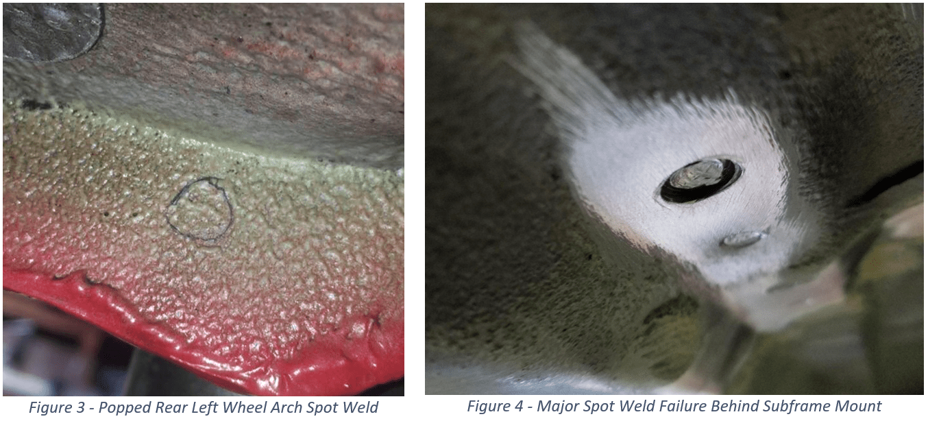
Unsurprisingly, spot weld failure is a product of fatigue and in fact just another example of crack formation. A spot weld often fails when a cracks forms around the perimeter of the weld in one or more of the multiple layers of sheet metal as shown in Figure 3. Eventually the crack will travel the full perimeter of the spot weld tearing out a hole in one layer and leaving the centre circle attached to the other layer as shown in figure 4. As a result, it isn't that the weld failed due to a lack of fusion or penetration but rather, the stress concentrated about its perimeter suffered fatigue.
In some areas of the RACP, this can also provide an initiation point for cracks to grow in multiple directions. A spot weld needs to be repaired from the side that has visible failure as shown below.
- Inspection – Inspect all the spot welds to confirm whether there is partial, full perimeter or propagating cracks visible.
Note: If a spot weld looks ok but, is very close to a noticeably failed spot weld, it's likely it may have some small cracks invisible to the naked eye and worth re-doing as per the below steps. - Prep the surface – The working area must first be stripped back to bare metal for repair. Use a wire wheel on a grinder (or rotary tool where needed) to strip undercoat & paint from the RACP. Do a final and gentle pass with a fine grit flap disk to remove primers exposing bright & shiny steel.
- Clean the surface – The raw metal can then be cleaned with and evaporative cleaner to prevent weld contamination.
- Remove the damaged material – The factory spot welds are ~6mm in diameter and can be drilled out using an 6-8mm spot weld drill bit when from the damaged side shown above.
Note: be sure to only drill through the torn layer and not entirely through the all layers.
Note: In places a drill cannot access, a carbide bit fitted to a rotary tool can be used to remove the damaged material. - Plug welding the hole – the newly drilled hole can now be filled with weld material producing a plug weld.
Note: Penetration about the perimeter is critical. Start from the centre then, do a small circular motion close to the perimeter of the hole then return to centre. This is the most effective method for plug welding.
Note: Use the crack repair method on any failed spot welds that initiated cracks.
Chassis Stitch welds;
In addition to repairing cracks and spot welds, several areas throughout the chassis are worth stitch welding to work in conjunction with the factory welds to reduce the stress on them while also increasing the strength and stiffness of the various joins between panels.
Stitch welding can be done along the edge of a layer of sheet metal where it overlaps another. It is suggested that all stitch welds are applied in no more than a 50:50 ratio along the welding edge.
There are many techniques of stitch welding with some doing large but individual tacks spaced very closely due to their small size and others stitching up to 1"/25mm long spaced proportionately. We personally prefer a greater quantity of short stitches or tacks as it provides better distribution and reduced heat input due to the shorter weld time.
As we are working with what's already there, we suggest applying a stitch between the existing spot welds rather than along side to make the load distribution along the edge of the panel as even as possible. Doing stitches alongside factory or repaired spot welds increases the localised heat input and increases thermal fatigue. This approach will generally dictate where your stitches will go leaving the length of your stitches (or tacks) at your own discretion. you may divide the gap between spot welds by whatever length and quantity of stitches you prefer provided the gaps between are equal to or greater than the stitches (or tacks) length.
- Prep the surface – The working area must first be stripped back to bare metal for welding. Use a wire wheel on a grinder (or rotary tool where needed) to strip undercoat & paint from the RACP. Do a final and gentle pass with a fine grit flap disk to remove primers exposing bright & shiny steel.
Note: A sharp (pick) tool and/or heat torch can be used to remove rubberised seam sealer or other materials stuck between layers. - Clean the surface – The raw metal can then be cleaned with and evaporative cleaner to ensure no weld contamination occurs.
- Mark out the stitches – Using either chalk or a marker, mark down the length of the panels edge where the stiches and spaces will be between the factory spot welds.
Note: Do not seem weld the entire edge. Stitch welds should follow these ratio's depending on application; Street < 1/3, Track < 1/2. - Stitch weld the join – Proceed to weld between the marks to achieve a stitch welded join.
Note: A series of tacks can be applied to create a short stitch weld.
Locations of Failure
Subframe Mounts & Rear Wheel Arches
As per the previous article the major points of interest are the rear subframe mounts (especially the rear left & front right) and the flange between the rear wheel arch and RACP behind the spring perch. These are the locations that generally fail first and thus the beginning of our investigation.
If any cracks or failed spot welds are found in these locations, please follow the above methodologies to repair the structure.

As shown in figure 2, the rear right wheel arch cracks on the inside at the top of the flange along the rear wheel arch, behind the spring perch as exterior edge was stitch welded from the factory preventing the spot welds from failing.
the rear left wheel arch on the other hand was not stich welded and the resulting spot weld failure can be observed on the inbound side of the flange where the panels join. Due to the location, it is often not possible to get a drill bit into the area so using a carbide bit as detailed above will be required to remove the damaged spot weld material. Be mindful that some of these spot welds may also initiate a crack that expands to the edge of the panel as shown in Figure 7.
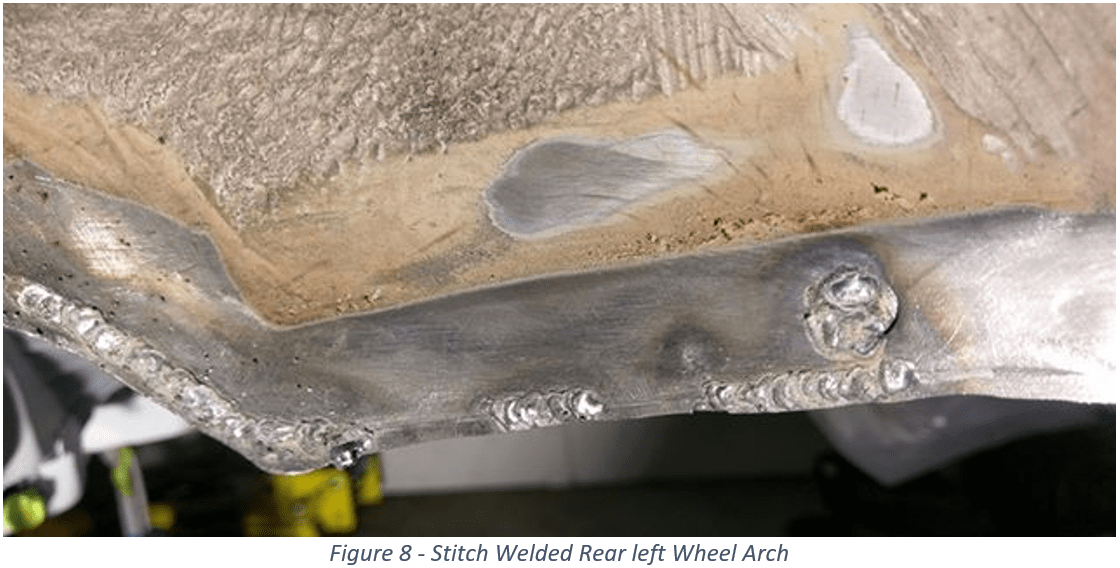
Once all the cracks and damaged spot welds in these areas are repaired, it is suggested that the left, rear wheel arch flange is stitch welded from the spring perch back on the exterior side using the Stitch Weld method detailed above as shown in Figure 8.

While our Underside Plates will reinforce any areas that fail at or in close vicinity to the rear subframe mounts, the rear wheel arch joins are a prime example of failure that will occur again in the exact same way (right side) or cause the cracks to form at the next weakest link (left side) without some form of topside reinforcement to correct the path the stresses take as they are distributed throughout the unibody chassis structure. (Refer to our Chassis Rail Plates or Rear Weld in Beam for a permanent solution.)
These areas are the first and primary points of failure within the RACP structure and if you’re lucky may be all the repair work needed prior to installing reinforcement kits with the exception of a few extra stitch welds.
However, if not addressed soon enough or reinforced preventatively, damage can spread to other areas of the RACP and surrounding structure resulting in additional cracks, failed spot welds and in some cases significant structural deformation.
The following areas and their mode of failure are listed in the order in which they are known to generally occur. The failure pattern is often consistent however, can vary and thus all areas should be inspected regardless of the extent of damage at the time of inspection/repair.
Chassis Rail to Boot Floor
The chassis rail is secured to the RACP via a series of spot welds along a flanged edge inside the boot in front of the spare wheel well.
To inspect this area, it is best to start beneath the car looking for broken spot welds inbound of the spring perch running from the rear two, rear subframe mounts to the front two, rear subframe mounts as shown in Figure 9. The spot welds closest to the subframe mounting points are the first to fail as per Figure 10.

If enough spot welds are allowed to fail, a gap often forms between the boot floor and chassis rail as per Figure 11. Deformation like this is not visible from above till things have escalated quite far. To inspect this area, you will need to remove the boot trim and potentially some sound deadening mat as shown below.
This type of failure occurs when the original load path (The rear wheel arch flange) fails and allows the RACP to flex downward causing it to peel away from the chassis rails.

If any spot welds have failed or look to have an unusually deep recess, repair them using the Spot Weld Repair Method detailed above. If a gap is present as shown in the above example, the deformation must be reversed and this gap closed before repairing and reinforcing the area.
Our Chassis Rail Plates will permanently prevent this failure from occurring again however, in the event they or any other topside reinforcements are not being installed, it is suggested that the chassis rails flanged edge is Stitch Welded to the boot floor from the spare wheel well to the rear seat backrest using the methodology detailed above.
Note: Drilling out the failed spot welds and inserting and tightening bolts before stitch welding the flange edge can close small gaps. Fill the holes when complete.

Behind the Rear Subframe Mounts
Looking just behind the rear two, rear subframe mounts, you will see where the RACP reconnects with the chassis rails highlighted in Figure 14. This area represents the rear most portion of the RACP and joins to the underside of the crumple structure either side of the spare wheel well.
The RACP is attached with a set of spot welds either side of the frame rail. To expose these spot welds, the seam sealer needs removing in the location shown in figure 15. These spot welds can then be repaired as per the Spot Weld Repair Method detailed above.
Failure in this location is also permanently resolved with appropriate topside reinforcement.

‘V’ Shaped Beam
The V shaped beam refers to a pressed metal beam that travels along the underside of the RACP between the front and rear, rear subframe mounts and can be seen just above the highlighted area in Figure 9.
It is possible for cracks to form at either end of this small beam where it terminates on the vertical face of the subframe mounts (generally rear two) as shown in Figure 16.
In the event cracks are present in this area, it can be repaired using the Crack Repair Method detailed above. This area is enveloped and reinforced by large coverage Underside Reinforcement Plates like ours.
Cracks are not often found in this area until after the the locations detailed above have suffered spot weld failure allowing the RACP to shift causing sufficient stress to redirect to this area inevitably leading to failure as shown below.

Topside of Rear Subframe Mounts
This area is not visible without cutting and thus, should be examined with an inspection camera to the best of your ability. In the event you do not have a port inspection camera, we recommend leaving this till the reinforcement project commences.
To access this area, the forward most portion of the spare wheel well within 5"/120mm of the chassis rails needs to be removed. Fortunately, exactly where to cut, drill and grind is detailed in the instructions for our Chassis Rail Plates and/or Rear Weld in Beam.
(in case we haven't made it clear, we do strongly recommend installing at least the Chassis Rail Plates along with Underside Plates when reinforcing your E46 chassis).
Once a section of the spare wheel well has been removed, the crack we're looking for can be seen just like in Figure 17. As you can see at the base of the crack, the point of initiation was a failed spot weld.
This spot weld is visible on the underside face of the rear left subframe mount as shown in figure 18 and should be repaired from beneath. Proceed to then use the Crack Repair Method if a crack is present.
Note: Be sure to check all the spot welds previously hidden beneath this panel for failure. The ones closest to the chassis rails & front of the car commonly let go first and are not visibly failed from beneath the car.

The above list concludes the areas specific to the rear two of four, rear subframe mounts. As we stated during each segment, all of these methods of failure thus far could be permanently resolved and prevented from ever happening again with just Underside Plates and Chassis Rail Plates (based on a few assumptions to be covered in later articles).
The coming areas to be detailed are are not common in all E46 shapes (coupe, sedan, convertible, Touring) due to the additional structure each shape may or may not have in comparison to others. For this reason, we will note which models it is likely or unlikely to occur in as we go.
We feel it's worth mentioning that although the following forms of failure are yet to be seen escalating to the same catastrophic levels the rear two mounts can, we recommend investigating these areas as thoroughly and seriously as the previous.
Many may not be familiar with these areas of failure and thus, very often go unnoticed during most reinforcement works and have heard some 'specialists' outright deny they occur at all. We want all our readers to have the best and most comprehensive reinforcement job possible and thus want to share every bit of information we can!
As you can imagine, we have developed a reinforcement kit for the topside of the front two, rear subframe mounts (Front Weld in Beam) to permanently repair, reinforce and prevent these areas from ever failing again however, it is only compatible with Coupe's & Sedans with split folding rear seats due to the structural differences mentioned above.
Rear Bench Seat to Chassis Rails
Common: Coupe, Sedans (with split folding rear seats)
Uncommon: Convertible, Touring, Sedans (with sheet metal wall)
Just like in the boot, the continuation of the floor beneath the back seats has a bad habit of not staying attached to the chassis rails and fails in the same fashion. This time, the spot weld failure is visible from above rather than below.
To reveal and inspect these spot welds, it's necessary to remove the heavy seams sealer along each frame rail from the back wrest down to the lowest point of the rear seat base as shown below.
If failed spot welds are found, repair them using the Spot Weld Repair Method. Proceed to also Stitch Weld the edge of the bench seat to the chassis rails to support the spot welds and help distribute the forces.

Chassis Rail to Boot Floor… Again
Common: Coupe, Sedans, Touring, Convertible
Uncommon:
Although we covered this in the first half, we thought this area would be worth mentioning again as the spot welds shown below are same as those found above at the very top of the seat base which sandwich the chassis rail between.
Both the top layer (rear seat bench) and bottom layer (RACP) can tear away from the chassis rail and thus, require spot weld repair from above and below.
As you can see comparing figure 21 & 22, when these spot welds fail the RACP does not pull down from the chassis rail as it does in the back half and due to the thick layer of undercoat, it can make the spot welds appear intact. Once the undercoat has been removed, the spot welds are commonly found to have failed and often even initiating cracks in various directions.
Use the Spot Weld Repair Method and Crack Repair Method detailed above to fix any failure discovered.

Around Rear Seat Anchors
Common: Coupe, Sedans
Uncommon: Convertible, Touring
Looking across the width of the rear seat base, there are multiple holes with female threads which serve as anchor points for various attachments (like seat belts) or have been plugged with plastic caps.
Although it can occur around any of these bolt holes, those closest to the chassis rails are the most common to fail first. Cracks generally form above the bolt hole and travel outward towards either side of the car as per the below examples.
Note: is is common for these cracks to have multiple fork points and can travel in any direction.

If cracks are found around any of the anchor points, use the Crack Repair Method detailed above to repair them.

RACP Front Edge
Common: Coupe, Sedans, Touring, Convertible
Uncommon:
Neglecting the RTA pockets, this area represents the most forward end of the entire RACP. This portion of the RACP is spot welded across its width to the underside of the rear seat base. As the rear seat bases sheet metal is thinner and weaker than RACP, the spot welds rip out of the top most layer, with failure being visible from within the cabin.
To reveal the location of these spot welds, it's necessary to remove the sound deadening matt bonded to the the rear seats base. Once exposed the failed spot welds will have torn about their perimeter just like previous.
Unfortunately, our development vehicle did not have this form of failure present and thus we don’t have any imagery of our own to share however, if failed spot welds are discovered, use the Spot Weld Repair Method from above.
To support these spot welds, we recommend applying Stitch Welds along the front edge of the RACP on both sides where it meets the seat base (top red line). Additional stitch welds can be applied between the RACP layers (bottom red line) as shown in Figure 27.

Front Two, Rear Subframe Mount Top Welds
Common: Coupe, Sedans, Touring, Convertible
Uncommon:
Failure in this area is very common on all E46 shapes and like many others detailed in this article, are often neglected during a reinforcement job and allowed to escalate.
This is once again a location that requires cutting into the floor of the cabin (and through multiple layers of the rear bulkhead on convertibles) to inspect correctly with no existing holes for a port inspection camera to enter. For this reason it is suggested that these top welds be inspected during the reinforcement works.
As shown in figure 28, we're inspecting the two MIG welds that contribute to securing the female threaded body inside the RACP that the front two, rear subframe fasteners screw into.
Note: The front left is less prone to failure than the front right however, not exempt.

These top welds are generally welded down one side of the slots as shown in figure 29 and generally crack at the top and bottom tips of the weld or, are completely filled as shown in figure 30 and will initiate at either a pin hole or some other weak point within the weld.

Repairing this area may require a unique approach in the even the slots are only welded down one side.
If so, before applying the Crack Repair Method for any failure discovered, use a carbide bit on a rotary tool to chew out the factory welds leaving the factory slots empty. Proceed to fill the entire slot with weld material as per figure 30.
Note: Follow the perimeter of the slot before returning to the centre just like a plug weld.
This concludes the list of potential problem areas associated with E46 rear subframe failure although, that isn't everything that can go wrong with an E46 as there are a few other problem areas that aren't resulting from the forces acting on the rear subframe mounts.
To not leave any stone unturned, we thought to add some honourable mentions.
Honourable Mentions
Rear Trailing Arm (RTA) Mount Pocket
Catastrophic rear trailing arm pocket failure is uncommon however, still probable none the less. In a worst case scenario, the spot welds securing the RTA pocket have the potential to shear out of the RACP as shown in Figure 31 & 32, resulting in the front of the rear trailing arm dropping from the vehicle. As you could imagine, if the rear wheel wasn't attached to the car and could point in any direction it wants, it would generally result in a fairly dramatic, complete loss of control leading to a serious and potentially fatal accident.
Given the severity of the consequence, we would have to strongly suggest that this area is also inspected and reinforced while you're tackling the other parts of the RACP.
To inspect the RTA pocket, look at edge of the flange inbound of the inner most bolt highlighted in Figure 33, for a slight split in the seam sealer. This is a sign the RTA is prying on the spot welds trying to tear it from the RACP.

To prevent catastrophic failure from occurring we need to offer support to the existing spot welds and better distribute the load around the perimeter of the flange.
Despite the fact that several well known brands sell a E46 RTA reinforcement plate, it is not necessary to reinforce this area and in our opinion shows how little they understand the E46 chassis.
E36's 100% do need RTA mount reinforcement plates to prevent failure (hence why we offer one for that generation) and because of the similar suspension, many assume E46's do to. The reason that is not the case is because, the E36's bolt holes were just short piece of tube tacked into the chassis. Cracks would form around the tack welds and down the arm comes. It is necessary to introduce a flange that gathers all three mounts and distributes the load around its large perimeter.
This is one of the improvements BMW made when designing the E46 generation and incorporated the bolt holes into an entire pocket with a large flange around the perimeter.
Use the Stitch Weld Method from earlier to stitch around the two edges highlighted in figure 35 with special attention to the radius around the most inbound bolt hole.
If there is a gap between the pocket and RACP, use the Spot Weld Repair Method on any suspect spot welds before stitch welding.

Front Strut Towers
The fact that the front strut towers crack on E46's (not the rear towers, that's an E36 thing again) is a pretty well known fact so we will keep this one short and sweet. Even BMW knew this was a problem when they were still making E46's and offered a reinforcement plate of their own to go between the top of the strut and below the tower.
BMW PN: 51717036781
What many people don't know is that cracks forming around the strut top and between the bolt holes isn't the only issue with the front strut towers.
One thing we've noticed over the years of reinforcing the E46 chassis (M3's in particular) is that the strut towers are prone to deform closer together over time. We've measured a significant difference in strut tower distance on many E46's with the most noticeable being between later M-cars that came with a strut brace from factory and the early counterparts that didn't.
When things really start to shift, a tear can be seen in the seam sealer and even pulling on the small gusset between the tower and front fenders.
To combat both these issues, we strongly suggest installing the BMW front strut tower plates (not the flat aftermarket ones, they don't do anything) and a sturdy (ideally single piece construction) front strut brace (not the stock M3 one, they snap the casting on top of the tower).
This combination will prevent the strut from attempting to punch up through the top of the tower and (if the strut brace is torqued with the wheels off the ground) support the static and dynamic (cornering, bumps etc) forces that would otherwise contribute to structurally deforming the towers together.
What Next?
We do apologise for this article becoming quite a lengthy read however, as we’ve said this issue is so much more complex than just fitting a set of underside reinforcement plates and calling it a day. There is a wide range of areas prone to fail and we believe they were all worth covering.
We consider any repair that hasn't inspected and addressed all the areas detailed in this article as incomplete and half baked.
Having to re-repaired many E46's in our local area, we strongly hold onto this opinion.
If your car has been reinforced by a previous owner or you're looking to buy a car that has been 'reinforced' (even if outsourced to a specialist), this information can be used to confirm that it was done correctly so you can rest assured you can drive your car with complete peace of mind.
If you want to learn more about why these areas fail and how our range of reinforcement products work prevent it happening again, we'd recommend reading out next article in the series: Part 3 - Stage 1 Underside Reinforcement.
How much reinforcement does my E46 need?
This will be detailed in the following articles however, what level of reinforcement is necessary comes down to many variable such as shape, age, state of existing failure as well as the owners long term plans for their vehicle. Not all customers can justify the full package of top to bottom reinforcement on their cars and we wouldn't encourage that.
This is where we appreciate the opportunity to discuss such things with our customers to tailor a package to suit their needs and goals while staying within their budget.
We've even taken the time to help some customers source equipment and educate them on the settings and techniques needed to DIY their own reinforcement when outsourcing is not financially viable.
The E46 chassis cracking is an issue that should not have existed in the first place (as the vast majority of cars don't) let alone be suffered twice.
Our goal is to help every E46 owner we can by sharing this information and hope, by doing so they consider what we have to offer and together, every reinforcement job will be as comprehensive and permanent as possible.
We at CMP would like to thank you for taking the time to read this article and hope you will continue to do so and keep us in mind for your current and future BMW projects and builds!
We'd like to give special thanks to our customer who choose to support and give us the opportunity to expand the range of products and resources we can offer so that we can continue to grow and give back to the BMW community.
Feel free to follow us on Facebook and Instagram to stay tuned on what we're working on!
Facebook: /cmpauto
Instagram: /cmp_auto_engineering